I'm starting a new project on esp32 - the task will be to download data from the serial port and save it in txt format on a pendrive. I am thinking about a 4x4 keyboard to set the time in the clock so that txt files in the name have the date and time of creation and an oled display to inform the user about the moment of saving data from the RS port to memory.

Below is the best information i found about UART ports on ESP32.
The UART is the serial protocol that allows easy data exchange between 2 devices. On the ESP32, 3 UART buses are available: UART0, UART1 and UART2. We can use them to communicate with a sensor, an Arduino, a Raspberry Pi, a computer …

The UART0 is by default on pins GPIO1(TX0) and GPIO3(RX0) of the ESP32. It is used to communicate with the computer through the serial monitor. It is also the one used to flash the ESP32 board when uploading a new program. It generally displays messages in the console with Serial.println() .

To use the UART2, simply add Serial2.begin() in the function setup() and to use the``Serial2.println()`` to send messages. By default, the UART2 bus is on pins GPIO16(RX2) and GPIO17(TX2), but you can change them (useful with a Wrover module) during setup. This simple code allows you to use the UART2 bus:

void setup() {
  Serial2.begin(115200);
}

void loop() {
  Serial2.println("Hello from UART2");
  delay(100);
}

The UART1 is by default on the pins used by the ESP32 flash. However, We can use it by choosing the pins you want, thanks to the “GPIO matrix” of the ESP32. Thus this code allows having a serial interface on the pins GPIO14 and GPIO12 by using the UART1 bus.

void setup() {
  /*
  * UART1  -> Serial1
  * RX Pin -> GPIO 14
  * TX Pin -> GPIO 12
  * UART Configuration -> SERIAL_8N1
  */
  Serial1.begin(115200,SERIAL_8N1,14,12);

}

void loop() {
  Serial1.println("Hello from UART1");
  delay(100);
}
Now i must connect UART port to machine which will send data thru RS port and catch it to ESP32 buffer.
Next thing is display some info on small OLED - so the user will see that cicruit is working and data was readed.
OLED display uses I2C communication protocol, so the wiring is very simple.
I use 4 cables - vin to 3.3v, gnd to gnd and scl to gpio22 and sda to gpio21.

Next i have to install Adafruit SSD1306 and GFX library into Arduino IDE.

The code is simple:

#include <SPI.h>
#include <Wire.h>
#include <Adafruit_GFX.h>
#include <Adafruit_SSD1306.h>

#define SCREEN_WIDTH 128 // OLED display width, in pixels
#define SCREEN_HEIGHT 64 // OLED display height, in pixels

// Declaration for an SSD1306 display connected to I2C (SDA, SCL pins)
#define OLED_RESET     -1 // Reset pin # (or -1 if sharing Arduino reset pin)
Adafruit_SSD1306 display(SCREEN_WIDTH, SCREEN_HEIGHT, &Wire, OLED_RESET);

void setup() {
  Serial.begin(115200);

  // SSD1306_SWITCHCAPVCC = generate display voltage from 3.3V internally
  if(!display.begin(SSD1306_SWITCHCAPVCC, 0x3C)) {
    Serial.println(F("SSD1306 allocation failed"));
    for(;;); // Don't proceed, loop forever
  }


  display.display();
  delay(2000); // Pause for 2 seconds

  display.clearDisplay();

  display.drawPixel(10, 10, WHITE);

  display.display();
  delay(2000);

//some text

display.clearDisplay();

  display.setTextSize(2); // Draw 2X-scale text
  display.setTextColor(WHITE);
  display.setCursor(10, 0);
  display.println(F("some text"));
  display.display();      // Show initial text
  delay(100);

}
Now i know that the problem is with USB pendrive flash drive.
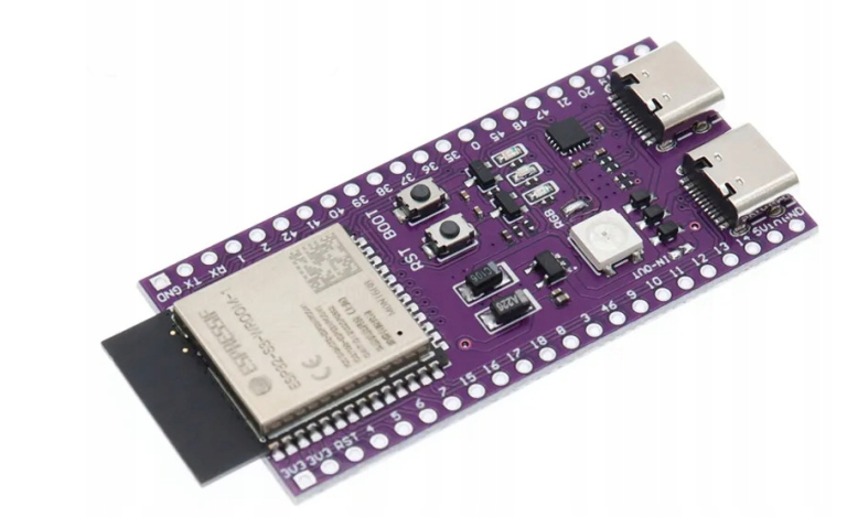
ESP32 does not have usb support by default so i must order ESP32 S3 and the project will be continued on this board.